With our everyday livings being more harmonized with green environment and surrounded by increasingly IA
(artificial intelligence)injected merchandise,battery packs based on different chemicals have become part of
our digital lifestyle.They exist,in various forms sizes,inside smart phones,wearables,laptops,electronic
toys,robot vacuum cleaners,E-bikes,power tools,UAVs (unmanned aerial vehicles),robots,power banks,
portable energy storage,NEVs(new energy vehicles)and the traditional ICE (internal combustion engine)
based vehicles.BMS (Battery management system)is instrumental to how well the battery pack operates and
how reliable the operation is.In typical operation,BMS first collects the state of charge of the battery pack,
analyze the loading and subsequently exchange the key information with the relevant sub-systems outside of
the battery pack.Along the way,BMS has to make balance act upon all the units inside the battery pack,
determine if any of the units is to be shut down,or be re-charged at a specific rate,or continue to release its
stored energy at a specific rate.All these decision must be made depending on the real-time condition inside
and outside of the battery pack,while safety must be ensured at all time.
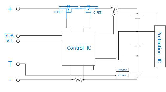
BMS
Regardless of the type of materials used in each renewable battery cel,BMS is a system capable of real-time
monitoring and management of battery pack.The electrical properties of each battery cell is monitored in real
time,diagnosis of the state of charge is subsequently carried out,warning are given and action are taken
whenever appropriate,charging/pre-charge/discharge and charge-balancing are executed in accordance to the
operating environment like thermal condition.Key objectives are:protect the battery cells from hazardous
damage,improve the health of the individual battery cells,ensure the safe operation of the aggregated battery
pack.
Why is BMS needed?
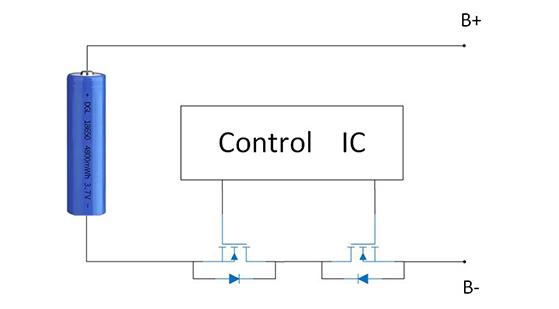
1.Safe operation of the battery pack:Over-discharge may cause permanent damage to battery cells.Over-
heated and over-charged battery cells may cause unexpected rupture and subsequent explosion
2.Functional requirements:During operation,it is necessary to know the capacity of the energy stored in the
battery pack in real time.Load Charge balancing must be vigorously taken care of in order to maintain the
good health of the battery pack.BMS achieves these by carefully controlling the operating temperature.
• With the pitch size between two neighboring cells smaller than 1um,die area of the MOSFET is optimized to
achieve the best power density possible
• Low intemnal ON-resistance and input gate charge contribute to the excellent condition and switching losses
of the MOSFET
• Because of good consistency upon the ON/OFF threshold voltage level across all MOSFETs manufactured,
bin management is trivial,multiple MOSFETs can be connected in parallel to facilitate large output current
without any of them being falsely turned ON
• All MOSFETs exhibit high UIS avalanche breakdown capability and are 100%screened for their UIS
performance at the FT (final test)stage during production
• Because these MOSFETs are housed in packages with outstanding thermal properties (i.e.low thermal
resistance),high level of continuous output current can be supported.
For BMS application,JJM offers MOSFETs housed in different packages and with VDS_Max covering 30~
200V.These components are based on either SGT or trench technology platform.System designers simply
choose the right MOSFET based on the loading requirement (e.g.power rating of the motor being driven)and
the output current needed.